How I built my furnace
Quote from Joshua States on May 29, 2024, 8:08 pmI built this furnace a little over a year ago and it's had a few minor tweaks since then, but the basic design is sound and working to spec.
This may take a few posts to get everything in here.
The furnace body is made from a standard BBQ size propane bottle. I made sure it was empty, spun the valve out and let it sit in the summer heat to fully evacuate any residue before cutting the top off and opening a top hole for exhaust. (first pic)I prepped the floor and lid the same way for the castable refractory. I used a product called Loucast. First a layer of 1" ceramic blanket (Superwool by Morgan Thermal Ceramics), some reinforcing wire, and then I poured the Loucast. A small round tube from a roll of packing tape blocked out the exhaust port in the lid (second pic)
The floor got the same prep and I poured it up to where the curved base met the vertical wall. (third pic) The square cut out in the wall is where the burner attaches.
I built this furnace a little over a year ago and it's had a few minor tweaks since then, but the basic design is sound and working to spec.
This may take a few posts to get everything in here.
The furnace body is made from a standard BBQ size propane bottle. I made sure it was empty, spun the valve out and let it sit in the summer heat to fully evacuate any residue before cutting the top off and opening a top hole for exhaust. (first pic)
I prepped the floor and lid the same way for the castable refractory. I used a product called Loucast. First a layer of 1" ceramic blanket (Superwool by Morgan Thermal Ceramics), some reinforcing wire, and then I poured the Loucast. A small round tube from a roll of packing tape blocked out the exhaust port in the lid (second pic)
The floor got the same prep and I poured it up to where the curved base met the vertical wall. (third pic) The square cut out in the wall is where the burner attaches.
Uploaded files: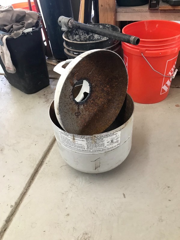
Quote from Joshua States on May 29, 2024, 8:25 pmThe burner you see in the above photo was an attempt at using a small ribbon burner. That didn't work so well and I had to make another burner.
I have made a few of these castable refractory burners and this is how I do it.
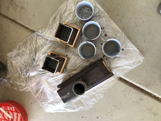
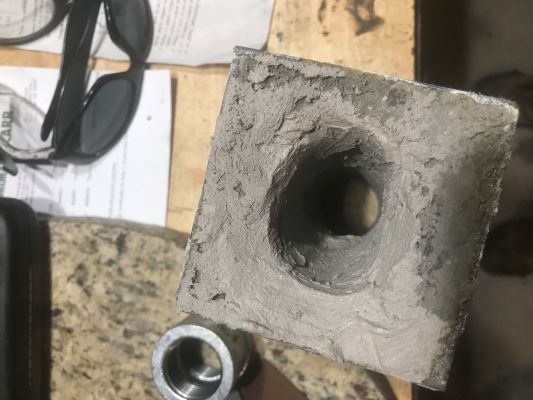
The burner body is basically a 4"x4"x4" square steel tube. There are some pieces of 1/8" thick by 2" wide steel plate welded to one end to take the poured refractory. (left side of pic 1)You want the burner to have a flare, sort of a conical shape that gets wider toward the inside of the furnace. You can do this two ways. You can fasion a cone shape out of plasting or card stock to place inside the frame body when you pour and remove it after the refractory is fully set, or you can pour the burner and cut the flare into the still soft refractory. I put the frames on a piece of plastic sheeting and pour the refractory into the body to fill past the weld line on te plate. (pic 2)
The finished flare is angled slightly to direct the flame to the side so it doesn't blow entirely directly on the crucible. (pic 3) The inlet opening on the backside of the burner is about 1" in diameter.
The burner you see in the above photo was an attempt at using a small ribbon burner. That didn't work so well and I had to make another burner.
I have made a few of these castable refractory burners and this is how I do it.
The burner body is basically a 4"x4"x4" square steel tube. There are some pieces of 1/8" thick by 2" wide steel plate welded to one end to take the poured refractory. (left side of pic 1)
You want the burner to have a flare, sort of a conical shape that gets wider toward the inside of the furnace. You can do this two ways. You can fasion a cone shape out of plasting or card stock to place inside the frame body when you pour and remove it after the refractory is fully set, or you can pour the burner and cut the flare into the still soft refractory. I put the frames on a piece of plastic sheeting and pour the refractory into the body to fill past the weld line on te plate. (pic 2)
The finished flare is angled slightly to direct the flame to the side so it doesn't blow entirely directly on the crucible. (pic 3) The inlet opening on the backside of the burner is about 1" in diameter.
Uploaded files: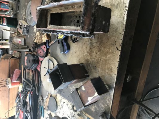
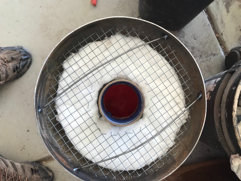
Quote from Joshua States on May 29, 2024, 8:42 pmThe walls of the furnace get the same prep work before pouring refractory. a 1" ceramic blanket, covered with some metal mesh (standard chicken wire) and a tube sized to create a central area for the furnace body. I sized this furnace for an A4 crucible and I happened to have a plastic plant bucket the fit almost perfectly to leave about an inch of refractory over the wool. (pic 1) A small piece of cardboard over the burner stopped any refractroy from plugging it.
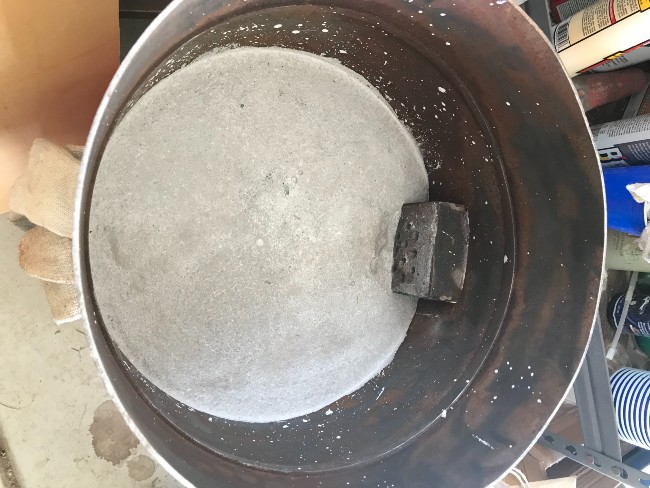
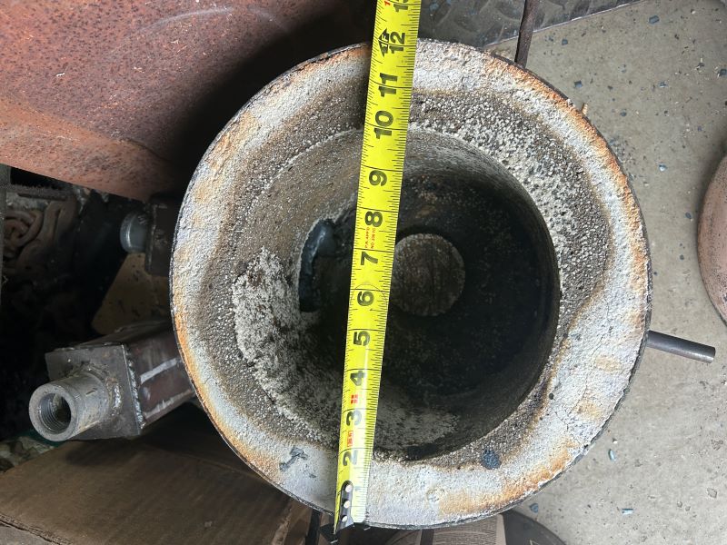
The finished chamber is about 8" in diameter (pic 2)
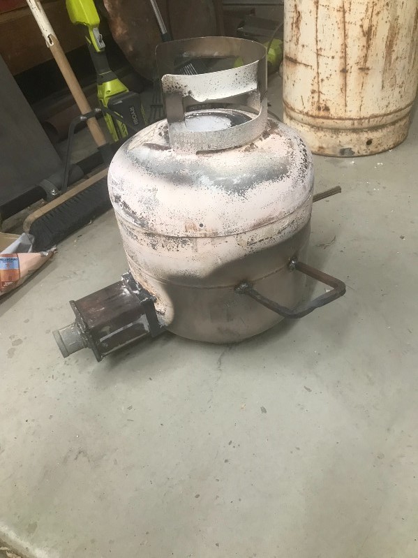
After everything is cured (about two days) I pulled the plastic pail ,lit a small wood fire inside the furnace, and covered it with the lid. I kept adding wood and let it burn for about two hours. I welded a couple of handles on the sides for easier handling, and this is the furnace when done. (pic 3)
You can see how I welded the back of the burner shut, cut a 1" diameter hole in the center of the back plate and welded a 1" pipe coupling over that hole. This is where the burner tube attaches,
The walls of the furnace get the same prep work before pouring refractory. a 1" ceramic blanket, covered with some metal mesh (standard chicken wire) and a tube sized to create a central area for the furnace body. I sized this furnace for an A4 crucible and I happened to have a plastic plant bucket the fit almost perfectly to leave about an inch of refractory over the wool. (pic 1) A small piece of cardboard over the burner stopped any refractroy from plugging it.
The finished chamber is about 8" in diameter (pic 2)
After everything is cured (about two days) I pulled the plastic pail ,lit a small wood fire inside the furnace, and covered it with the lid. I kept adding wood and let it burn for about two hours. I welded a couple of handles on the sides for easier handling, and this is the furnace when done. (pic 3)
You can see how I welded the back of the burner shut, cut a 1" diameter hole in the center of the back plate and welded a 1" pipe coupling over that hole. This is where the burner tube attaches,
Uploaded files: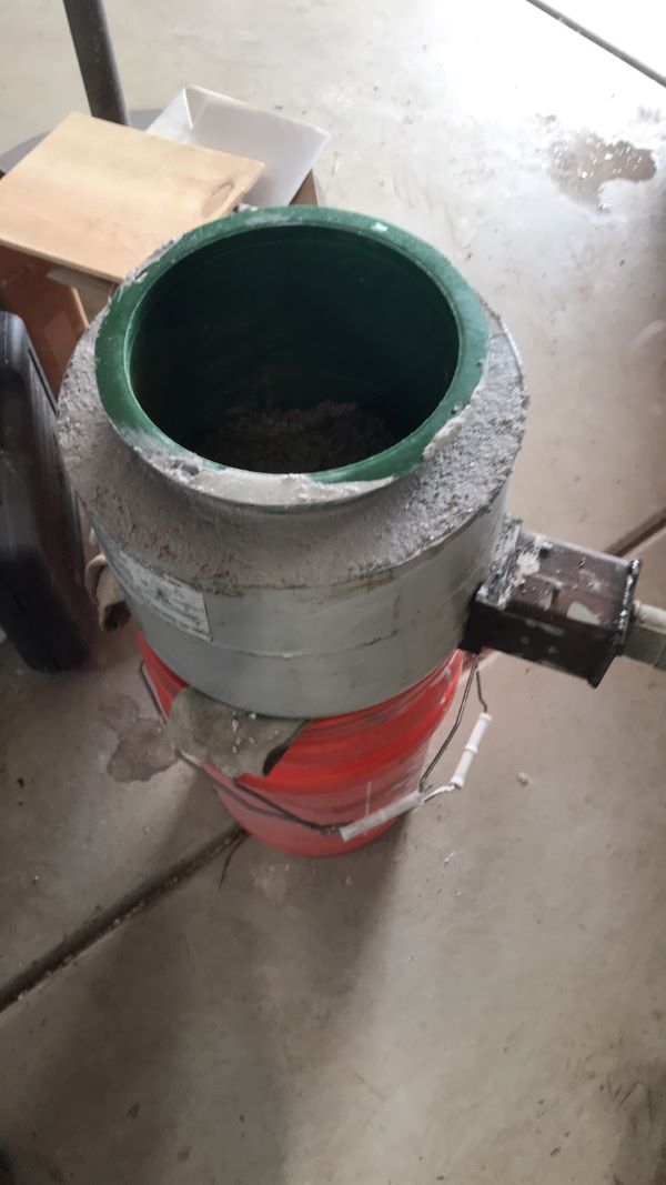
Quote from Jacob Christian on May 30, 2024, 1:43 pm@joshua-states
This furnace looks fantastic! I ended up taking the same route with the cast burner in my furnace, though slightly different. Then you dont have to worry about the tip of your burner melting off. Been there a few times.....
On a side note, if the loucast is not low thermal mass your furnace will take much longer to get up to temp.
Quote from Joshua States on May 30, 2024, 8:56 pmI have to check my notebook, but I think I get to 1000C in about 15 minutes and another 15-20 to get to 1550C. I hold for 20-30 minutes for a 1kg charge.
All in it's about an hour to melt.More pics of the whole burner/blower setup tomorrow.
I have to check my notebook, but I think I get to 1000C in about 15 minutes and another 15-20 to get to 1550C. I hold for 20-30 minutes for a 1kg charge.
All in it's about an hour to melt.
More pics of the whole burner/blower setup tomorrow.
Quote from Joshua States on May 31, 2024, 7:09 pmThere have been some minor mods to the burner/blower assembly since I first built it. The first thing to make is the gas feed as this is a propane fired furnace.
WARNING: Making a propane burner assembly is dangerous business. You could get seriously injured or die using this type of homemade device. If you have any doubts at all about your ability to run gas piping, don't do this. Buy a premade burner from a reputable supplier.
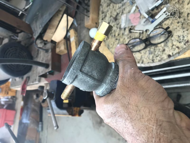
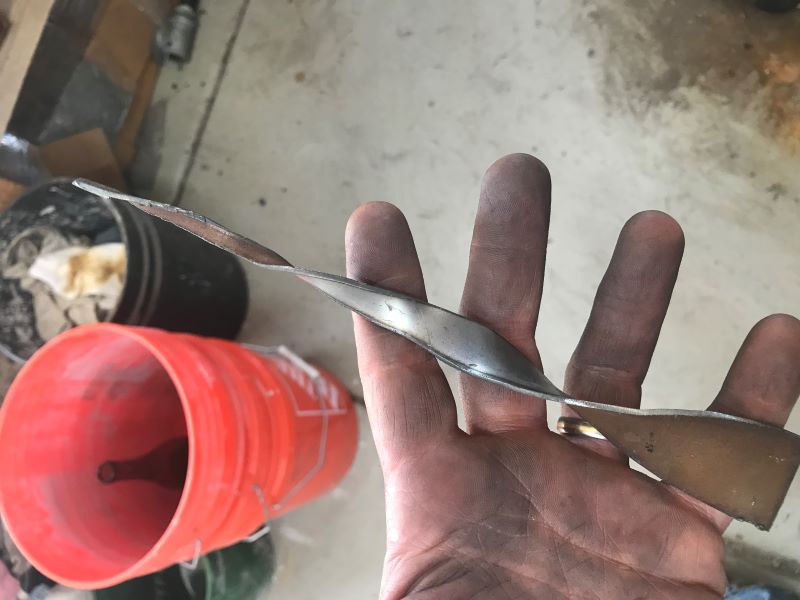
The orifice started out as a 1/16" hole in a 1/4" brass pipe. I have since enlarged that hole to about 7/64" if memory serves. (pic 1)The burner tube is an 18" long black gas pipe nipple with a reducer coupling that adapts the 1" pipe to 1-1/4" pipe. I drilled a hole through the larger end of the reducer coupling to slide the brass pipe through. (pic 2) One end of the brass pipe is capped off and the other end is where the propane feed comes in. The brass pipe is set with the drilled orifice hole pointing straight down the center of the 18" long pipe nipple.
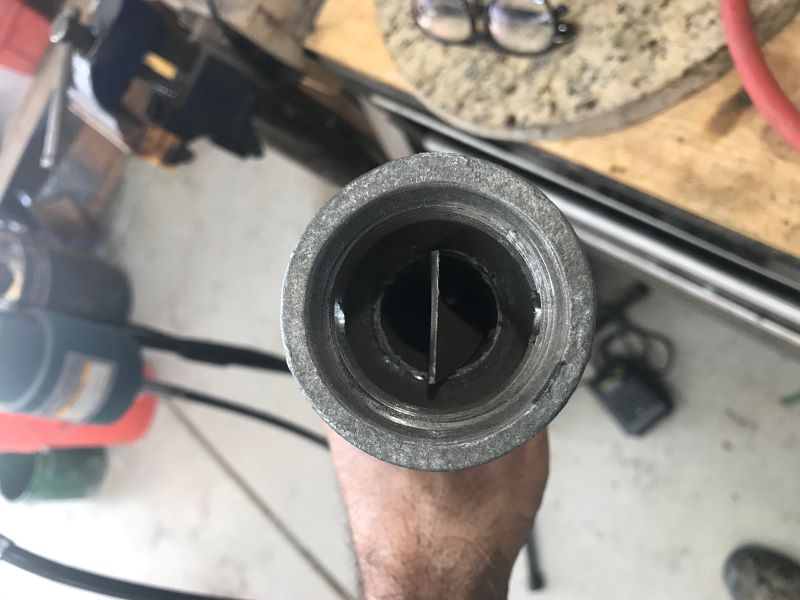
There is a mixing plate inserted into the pipe. (pic 3) This is a 12" long piece of thin sheet metal cut into a triangle fom about 1" on one end to zero on the point. This is then twisted to form a helix. (pic 4)
There have been some minor mods to the burner/blower assembly since I first built it. The first thing to make is the gas feed as this is a propane fired furnace.
WARNING: Making a propane burner assembly is dangerous business. You could get seriously injured or die using this type of homemade device. If you have any doubts at all about your ability to run gas piping, don't do this. Buy a premade burner from a reputable supplier.
The orifice started out as a 1/16" hole in a 1/4" brass pipe. I have since enlarged that hole to about 7/64" if memory serves. (pic 1)The burner tube is an 18" long black gas pipe nipple with a reducer coupling that adapts the 1" pipe to 1-1/4" pipe. I drilled a hole through the larger end of the reducer coupling to slide the brass pipe through. (pic 2) One end of the brass pipe is capped off and the other end is where the propane feed comes in. The brass pipe is set with the drilled orifice hole pointing straight down the center of the 18" long pipe nipple.
There is a mixing plate inserted into the pipe. (pic 3) This is a 12" long piece of thin sheet metal cut into a triangle fom about 1" on one end to zero on the point. This is then twisted to form a helix. (pic 4)
Uploaded files: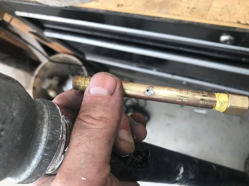
Quote from Joshua States on May 31, 2024, 7:38 pmAttachig the propane and blower.
This is the gas/air valve assembly (pic 1). The hose is coming from the regulator on the propane tank. It feeds a 5-poition valve that has detents to tell you when the valve is off to fully open in 1/4 turn increments. That feeds a Tee with a pressure gauge. The red handle is a 1/4" shut off valve connected to the brass pipe. The brass pipe is held in place firmly by a 1-1/4" nipple. This is the air intake from the blower. The big yelow handle is the ball vlave to adjust the air flow. This has since been replaced with a gate valve because it was too diffficult to get minor airflow adjustments with the ball valve. Small changes in airflow yeild large changes in temperature and oxidation levels. The gate vlave allows for very small changes to the airflow. There is a 1-1/2 inch hose attached to another 1-1/4" nipple in the other end of the air valve. That hose is standard pool/spa hose and you can get it at any home improvement warehouse or pool supplier by the foot.Pic 2 is the whole assembly attached to the furnace. The 1" x 18" burner tube is screwed into the back of the burner with the valve assembly already attached to the tube. The hose is then held onto the valve assembly with a hose clamp and the other end of the hose is attached to a blower. This blower has since been replaced with a smaller blower that is much quieter and blows less air.
Attachig the propane and blower.
This is the gas/air valve assembly (pic 1). The hose is coming from the regulator on the propane tank. It feeds a 5-poition valve that has detents to tell you when the valve is off to fully open in 1/4 turn increments. That feeds a Tee with a pressure gauge. The red handle is a 1/4" shut off valve connected to the brass pipe. The brass pipe is held in place firmly by a 1-1/4" nipple. This is the air intake from the blower. The big yelow handle is the ball vlave to adjust the air flow. This has since been replaced with a gate valve because it was too diffficult to get minor airflow adjustments with the ball valve. Small changes in airflow yeild large changes in temperature and oxidation levels. The gate vlave allows for very small changes to the airflow. There is a 1-1/2 inch hose attached to another 1-1/4" nipple in the other end of the air valve. That hose is standard pool/spa hose and you can get it at any home improvement warehouse or pool supplier by the foot.
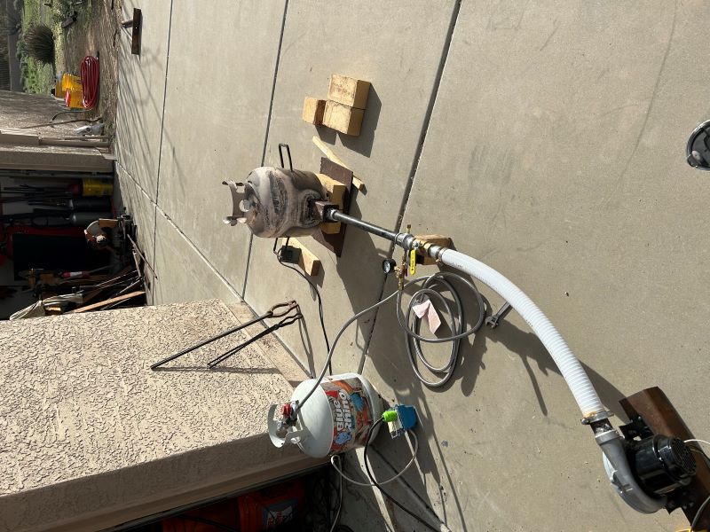
Pic 2 is the whole assembly attached to the furnace. The 1" x 18" burner tube is screwed into the back of the burner with the valve assembly already attached to the tube. The hose is then held onto the valve assembly with a hose clamp and the other end of the hose is attached to a blower. This blower has since been replaced with a smaller blower that is much quieter and blows less air.
Uploaded files: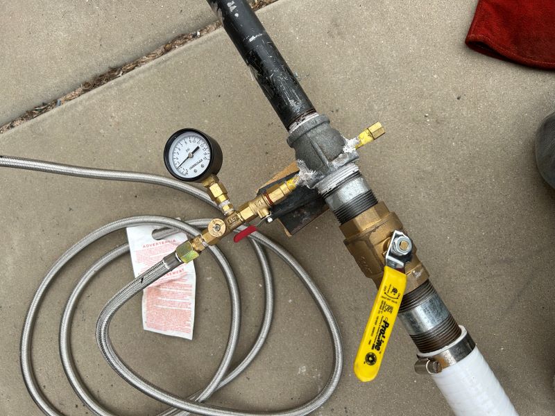
Quote from Jacob Christian on June 12, 2024, 7:17 amVery interesting setup for the propane. I have mine just dump the propane straight in, no orifice.
Very interesting setup for the propane. I have mine just dump the propane straight in, no orifice.
Quote from Joshua States on June 14, 2024, 6:31 pmQuote from Jacob Christian on June 12, 2024, 7:17 amVery interesting setup for the propane. I have mine just dump the propane straight in, no orifice.
How big a propane bottle do you use and how many melts per bottle? I can get two melts from a standard BBQ size (20#) and double that for the new 40# bottle.
Quote from Jacob Christian on June 12, 2024, 7:17 amVery interesting setup for the propane. I have mine just dump the propane straight in, no orifice.
How big a propane bottle do you use and how many melts per bottle? I can get two melts from a standard BBQ size (20#) and double that for the new 40# bottle.
Quote from Jacob Christian on June 18, 2024, 11:22 amI have a 100lb bottle and idk probably 8+ melts. I suppose my statement of no orifice is not entirely true, there is a needle valve that controls the flow.
I have a 100lb bottle and idk probably 8+ melts. I suppose my statement of no orifice is not entirely true, there is a needle valve that controls the flow.